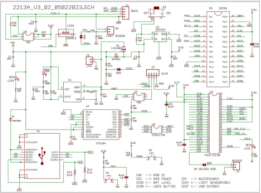
 |
|
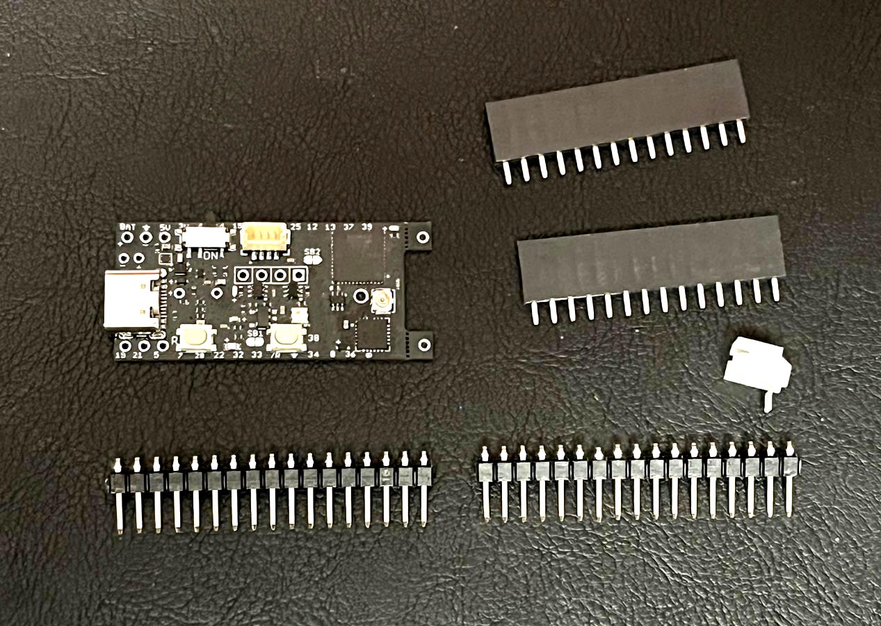
1. Parts included in the package:
One
NanoboyPICO-V3-02 board.
Two 1x17 right-angle male headers.
Two 1x14 female headers.
One
2-pin JST connector, 2mm pitch.
|
|
|
|
|
 |
|
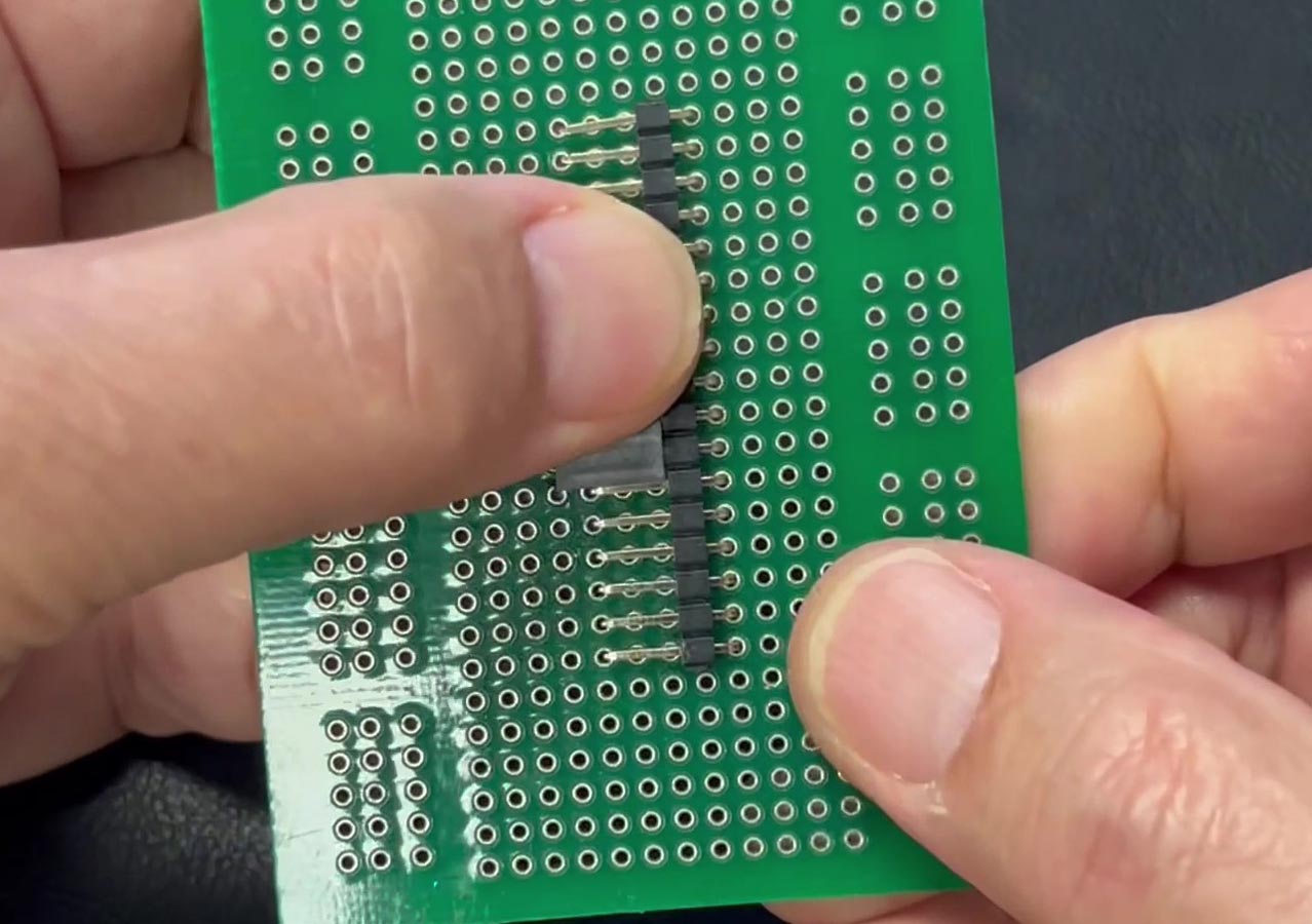
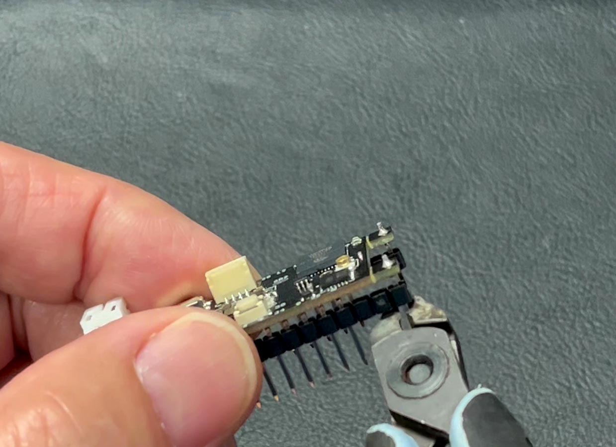
2 Place the shorter end of the 1x17 right
angle male header on a prototype PCB.
The length of the pin is longer than 1.6mm. So
flush cut the 16 pins to the PCB to make the
length shorter.
See the video clip |
|
|
|
|
 |
|
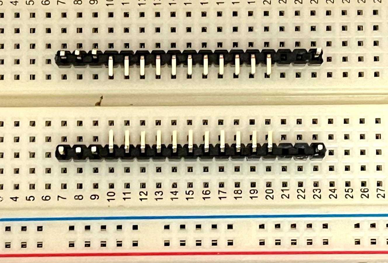
3 Bend 3 pins on each end of the 1x17 male
header and make them straight.
place them on a table as shown on the
picture.
Be sure to place the long pins in the middle.
Use a pair of pliers to pull out 2 pins next to the right-most pin out
of each header as shown on the picture.
The right-most pin is a helper-pin for securing
the header position during soldering. It will be
broken off after soldering is done.
See the video clip
|
|
|
|
|
 |
|
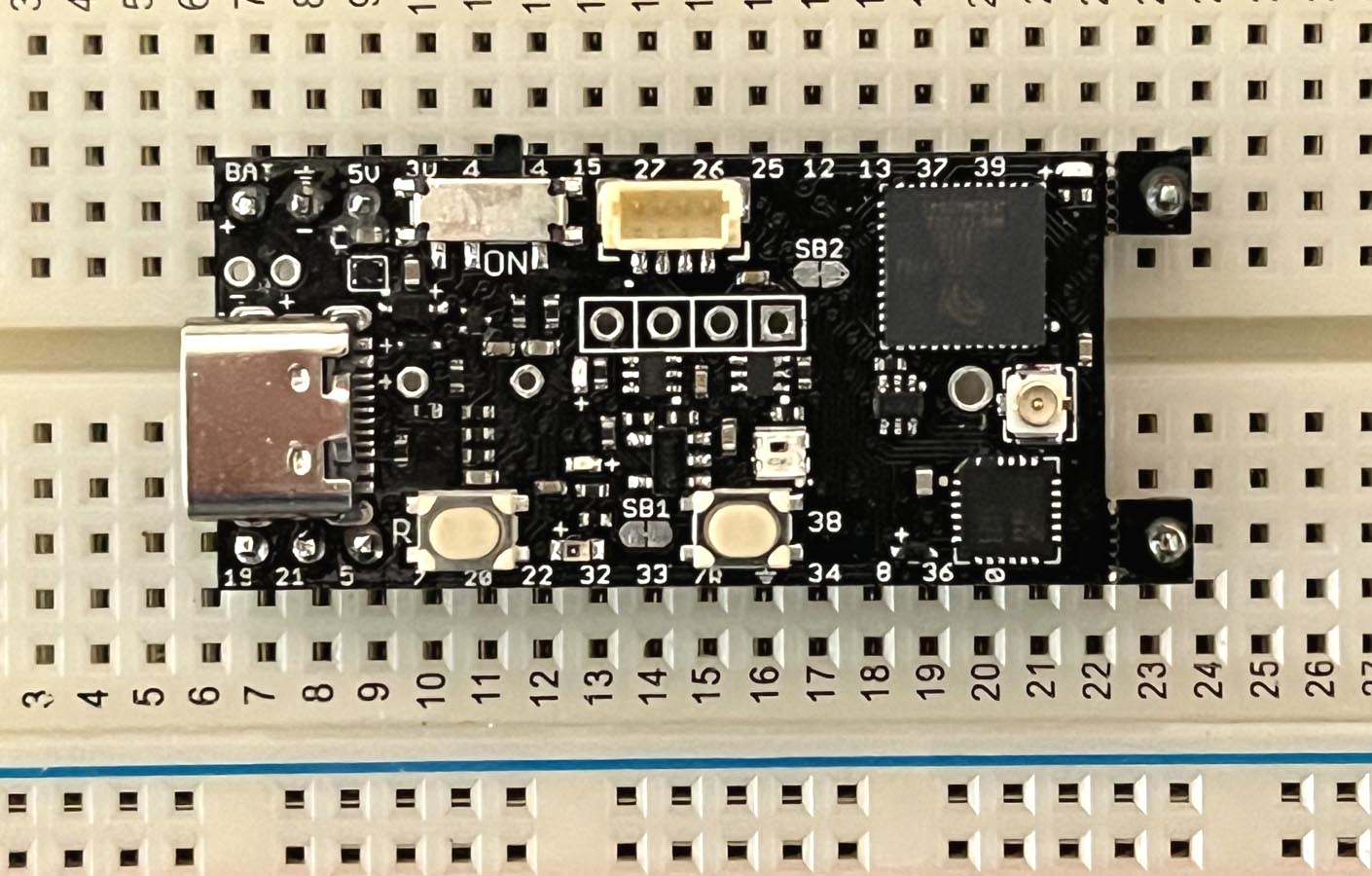
4. Place the 2 modified male headers on a
breadboard 0.6" apart as shown on the picture.
|
|
|
|
|
 |
|
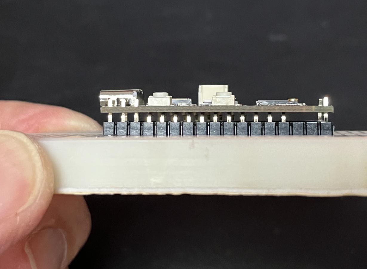
5. Place the NanoboyPICO board over the headers.
Press it down and make sure the board is
leveled.
Solder 4 corner pins first. When
soldering the first corner pin, press down the board
at the middle so the board will be leveled
even you apply pressure on a corner pin during
soldering. After soldering the 1st corner pin
make sure the board is leveled. Check it as
shown on the next picture.
Finally solder all other remaining pins. |
|
|
|
|
 |
|
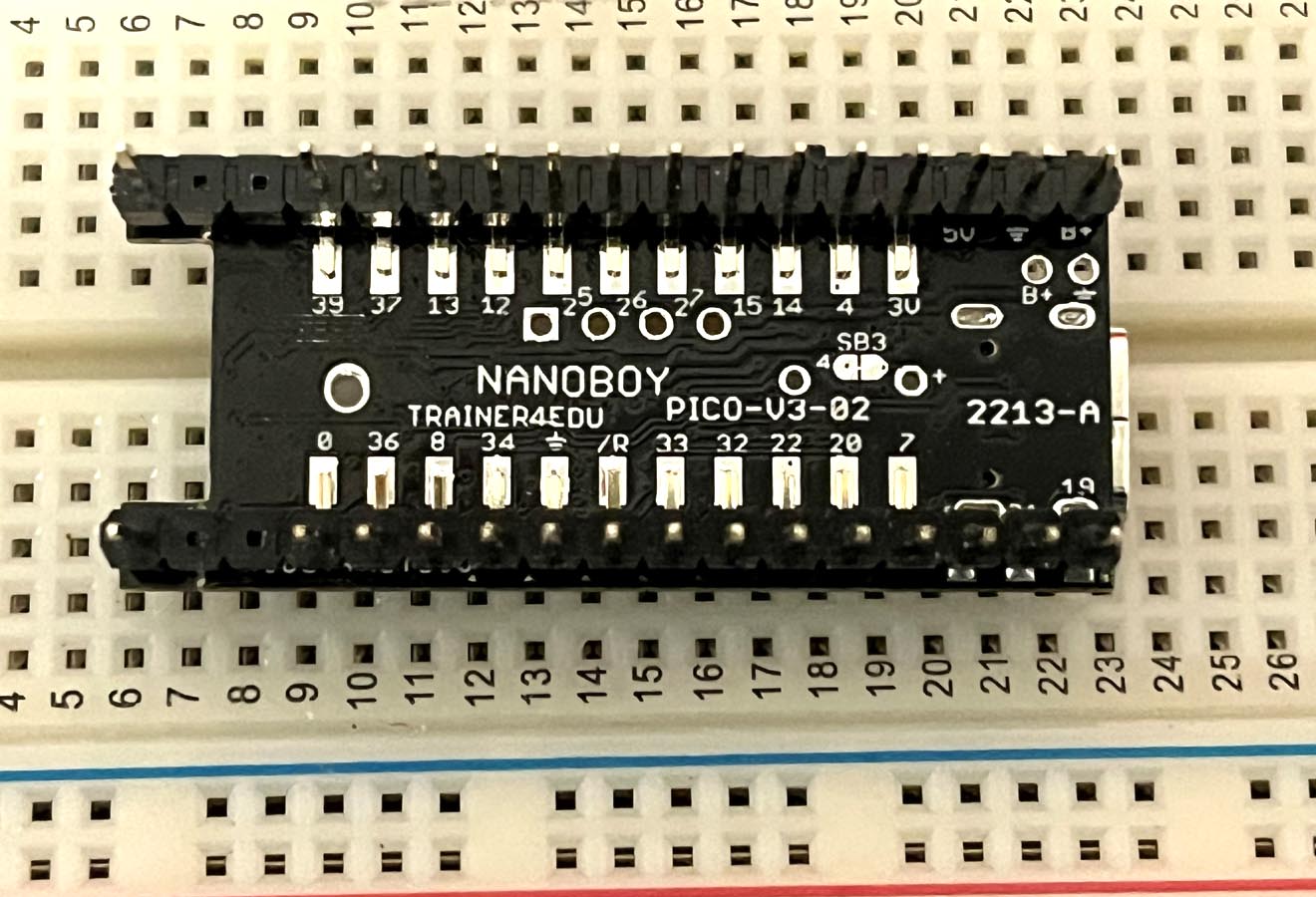
6. After soldering all pins on the top you
should see the side view of the board like this. |
|
|
|
|
 |
|
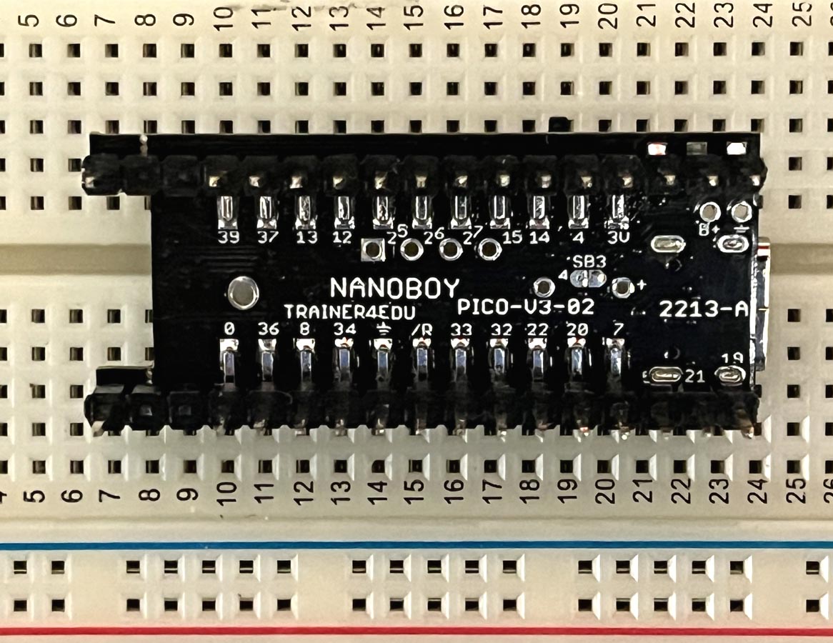
7. Take out the board from the breadboard and
flip it over.
Add a lot of solder flux on all remaining pins at the
bottom, then solder every pin. |
|
|
|
|
 |
|
8. All pins at the bottom are soldered and water
soluble flux residual is cleaned up.
In the recent 30 years I use water-soluble flux only. because it's
much easier for soldering. The solder
joint is also very shining. For production
quantity I can wash
away the flux residual with a dish washer. For
small prototypes
I just brush some
water to clean the spot. After that I will
shake off the water and use napkin to wipe
water away. Make sure use a heat gun or a hair
dryer to dry the board if you need to test it
immediately.
If you use non-clean flux, you need to use 90%
Isopropyl Alcohol to clean up solder residual. |
|
|
|
|
 |
|
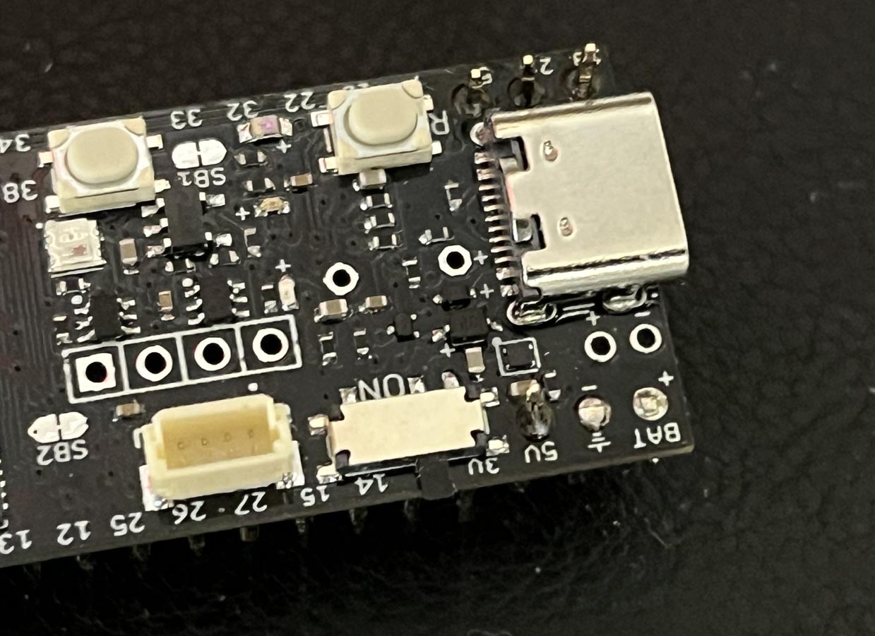
9. Flush cut two battery connector pins at the top. Use
90% Isopropyl Alcohol to remove solder residual of
non-clean flux or just water to remove solder
residual of water soluble flux.
Then solder the JST connector. After soldering one pin check if the connector
is perfectly in the horizontal position. If not,
you can adjust it when heating the pin. When the connector is perfectly in the horizontal
position, then solder the other pin .
|
|
|
|
|
 |
|
10. Cut the helper-pins away and break off 2
small pieces of the PCB.
Then break off the
extra plastic body on the male headers.
See the video clip
|
|
|
|
|
 |
|
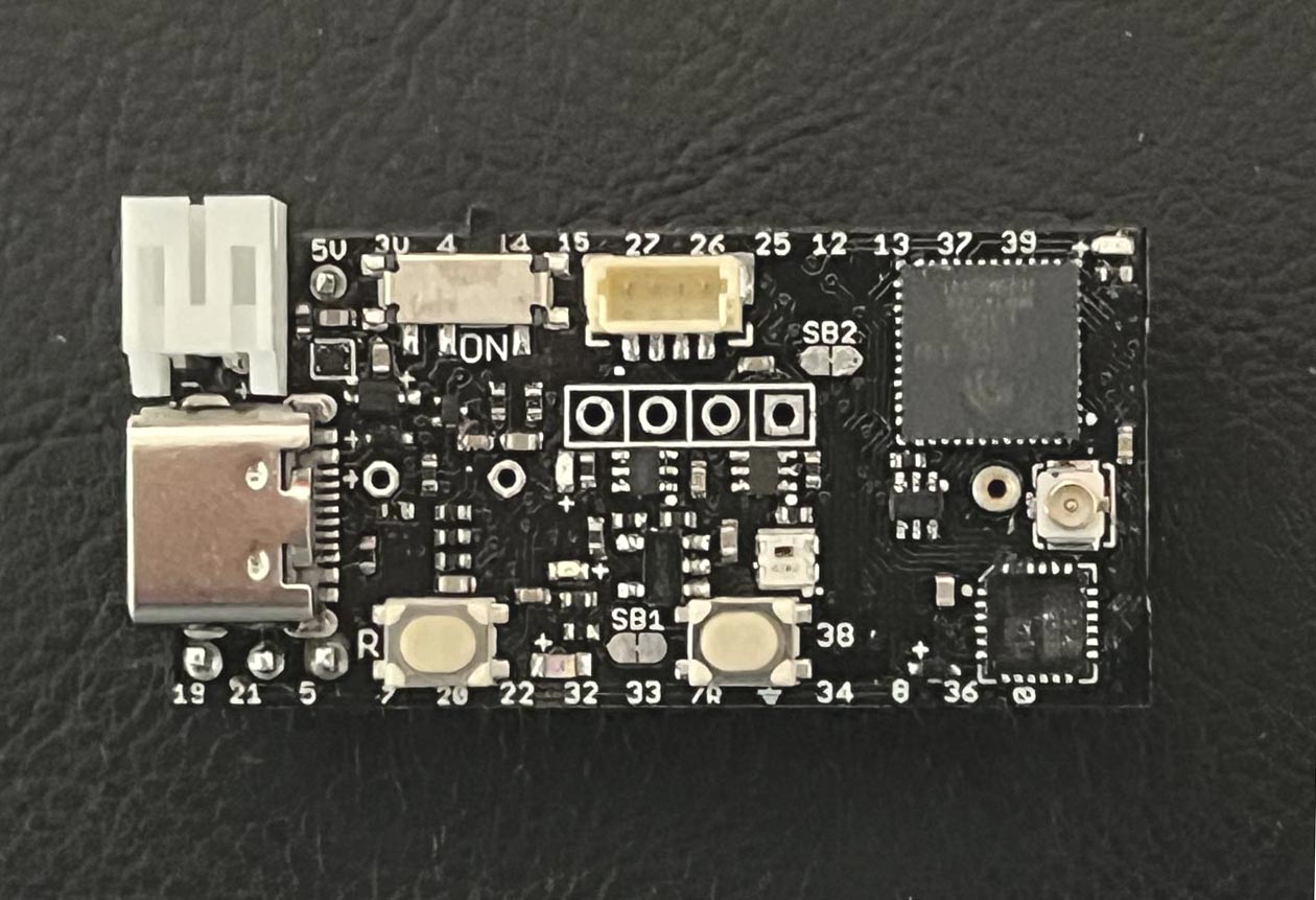
11. This is the final assembled board.
Take care of the LiPo battery connector. When you need to unplug a battery cable hold the
connector with one hand and unplug the cable
with the other hand.
Since the board has a power switch, you can
turn off the switch instead of unplugging the battery cable and
USB cable. The power switch only
disconnect the power to the LDO. So it
disconnects the battery but not the USB 5V. The 5V LED will
still be ON as long as the USB is plugged in,
but the current from a USB hub is very insignificant
when the power switch is in OFF position. |
|
|
|
|
 |
|
12. If you want to play the Flappy Bird
game, you need to solder an active buzzer and a
0.96" OLED.
Most DIY makers probably already have a 0.96" OLED
display. |
|
|
|
|
 |
|
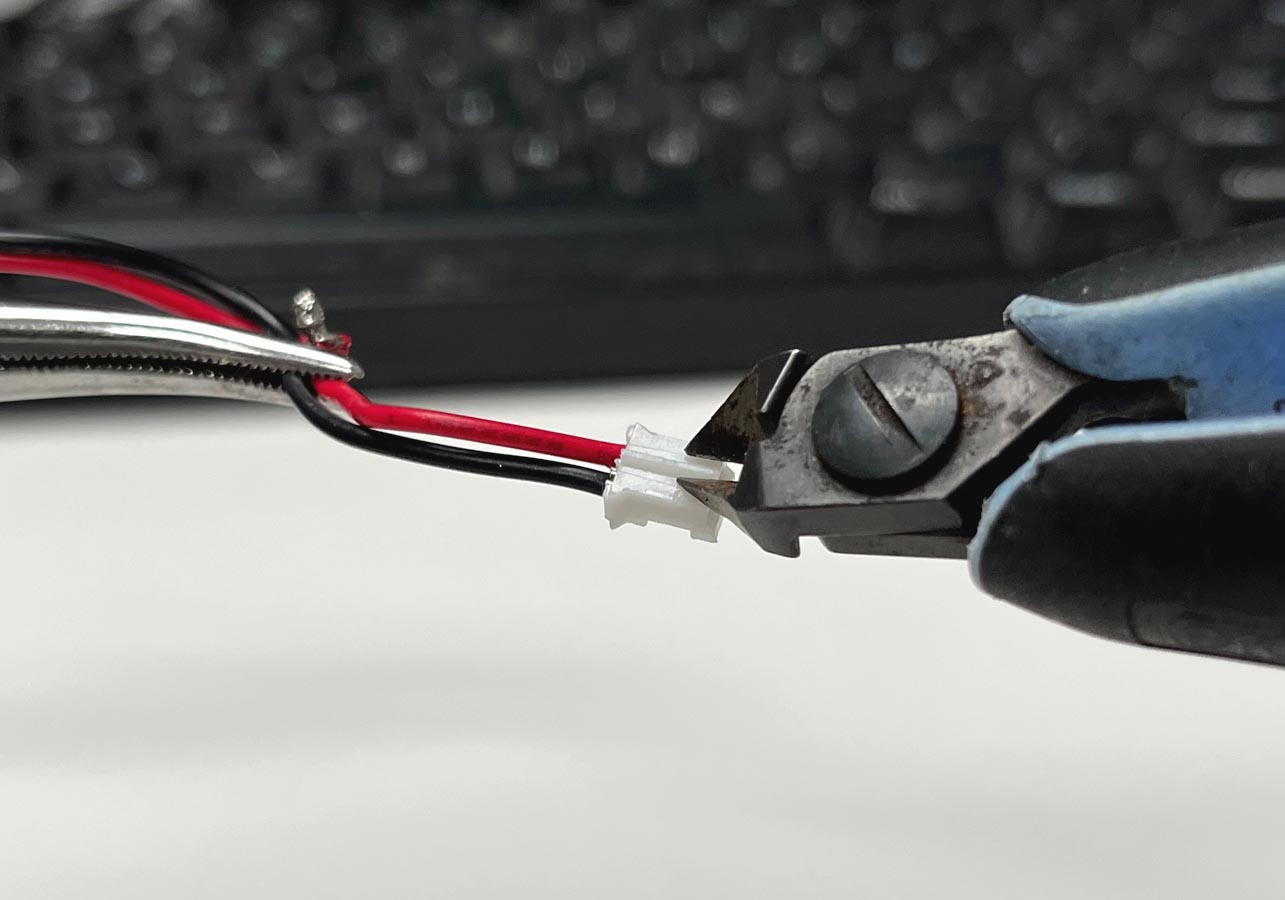
13. Cut off the tab on a battery cable
connector.
Sometimes the the battery connector is too tight
and hard to pull the cable out. You can cut off
the tab in the middle, otherwise you may pull
out the connector from the PCB.
|
|
|
|
|
 |
|
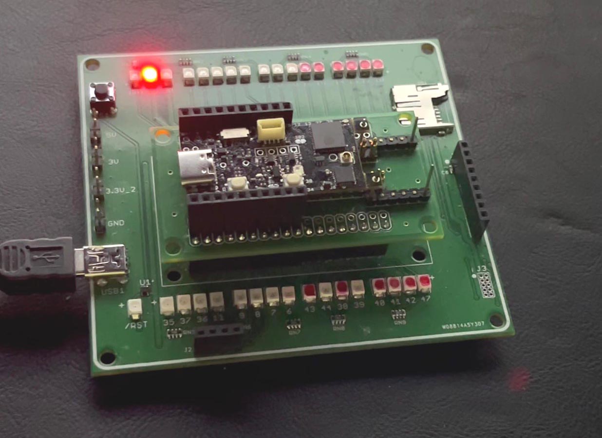
A makeshift test jig (for both NanoboyPICO-V3-02
and NanoboyS3)
The NanoboyPICO-V3-02 is preloaded with a test sketch
that will flash all output pins.
After you receive it, you should try to upload
the Blink-A-LED example sketch before soldering all male
pins. |
 Trainer4Edu.com
SmallPICO.com
Nanoboy.com
Flappy Bird


